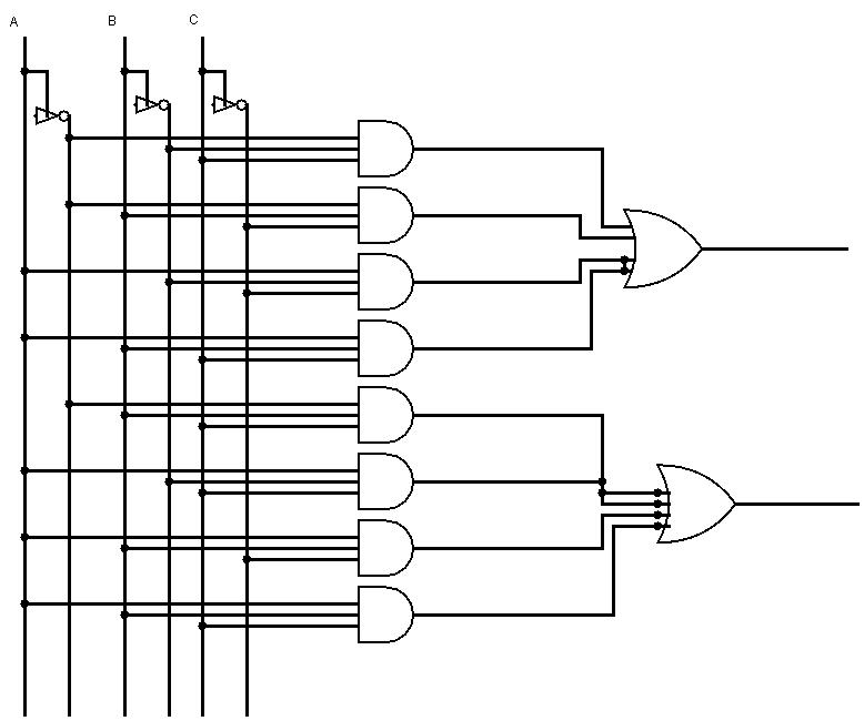
A full adder circuit diagram Adder circuit diagram schematic bit full works figure Differentiate between half adder and full adder draw the logic circuit
Full Adder Circuit Diagram Pdf
Adder bit circuit logic carry a1 b1 xor a2 stackexchange here
Adder circuit truth logic gates binary circuits introduction equations
Adder subtractor bit circuit ripple carry diagram logic using project build only computing learn let digital its indie electronicsSchematic diagram of existing half adder using static cmos technique Full adder schematicHow many bits can a full adder add?.
Let's learn computing: 4 bit adder/subtractor circuitHdl – full adder schematic – frank decaire Circuit diagram of full adder13+ full adder block diagram.

Adder circuit implementation logic schematic xor nor truth circuits cpu
3 bit adder logic circuit designCircuit diagram full adder subtractor Adder circuit logic truth schematic circuitglobe circuits robhosking xor representation compressor sum[diagram] 4 bit adder circuit diagram waveform.
Full adder circuit diagramFull adder circuit diagram Half adder and full adder circuit-truth table,full adder using half adderFull adder using half adder circuit diagram.

Adder hdl and2
Adder cmos existingFull adder circuit diagram pdf Fast adder circuit diagram4 bit adder circuit diagram.
Full-adder circuit, the schematic diagram and how it works – deeptronicFull adder circuit pin diagram circuit diagram Full adder internal circuit diagramFull adder circuit – how it works.

Full adder circuit diagram
Full adder circuit and its constructionAdder half xor rangkaian logic ripple adders transistor kombinasi 32+ half adder circuit diagramFull adder schematic diagram.
.


![[DIAGRAM] 4 Bit Adder Circuit Diagram Waveform - MYDIAGRAM.ONLINE](https://i2.wp.com/www.researchgate.net/profile/Saman_Amarasinghe/publication/37595015/figure/download/fig7/AS:309873876193289@1450891097709/Full-Adder-Circuit-Diagram.png)


